My kids and I decided to make a robot with the Raspberry Pi my brother gifted us a few years ago. I did a quick search for an easy robot to make and landed on this tutorial.
Here’s a list of all the things we’re using and where we got them from (all from Amazon, so items may become unavailable and/or links may break):
- Already had the following: Raspberry Pi, laptop/peripherals, SD card, 4 AA batteries
- IR sensor modules
- robot chassis, wheels (2 fixed + 1 caster), geared DC motors, AA battery connector (total of 6V)
- L293D driver board (See below for why we ended up using this board instead, though.)**
- bread board, male-male jumpers, female-female jumpers, push button
We got started by following the Raspberry Pi Noobs Setup video to download/install Raspbian to the SD card. After inserting the prepped SD card into the Raspberry Pi (RP) we needed to hook the RP up to peripherals, power and internet. To do this we used the following things from around the house:
- TV + re-purposed HDMI cable from the DVD player
- USB keyboard
- USB mouse
- charger + micro USB cord from my Nexus 4 phone
- wifi extender + ethernet cable
This was my first time hooking up the Raspberry Pi so I was happy to see how easy it was to get going with stuff I already had.
 After installing Raspbian, which took a while, we took a break to play some of the games in the python-games directory and to check the weather. Then we got going on Step 1 of the tutorial.
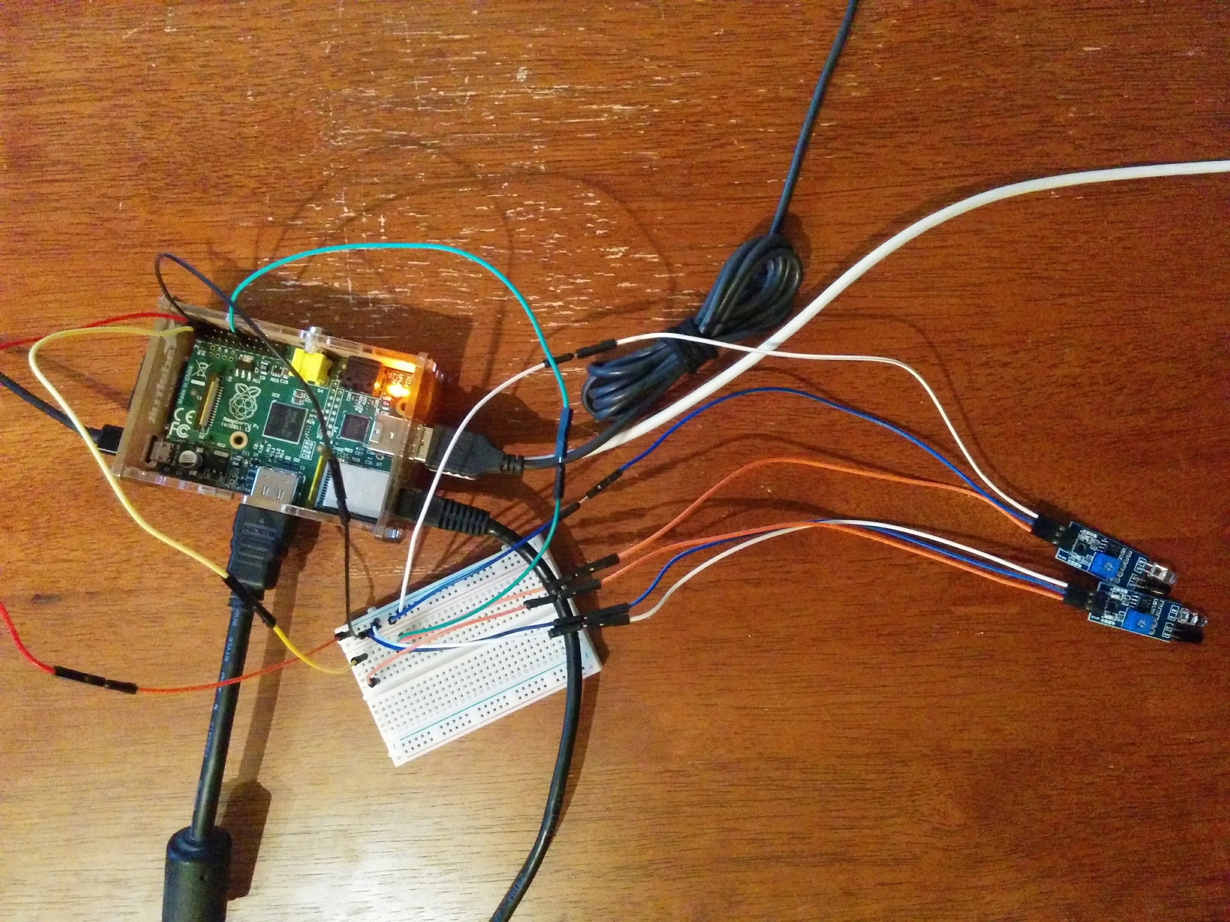
Step 1: Testing the IR sensors. This worked fine. For the infrared (IR) sensors we bought, expect one light on top to turn on once the VCC, ground and negative terminals are hooked up correctly to the appropriate GPIO pins on the powered up RP. Then put a hand or something in front of each sensor and if it’s detected the other light should also turn on. Here’s our setup so far:
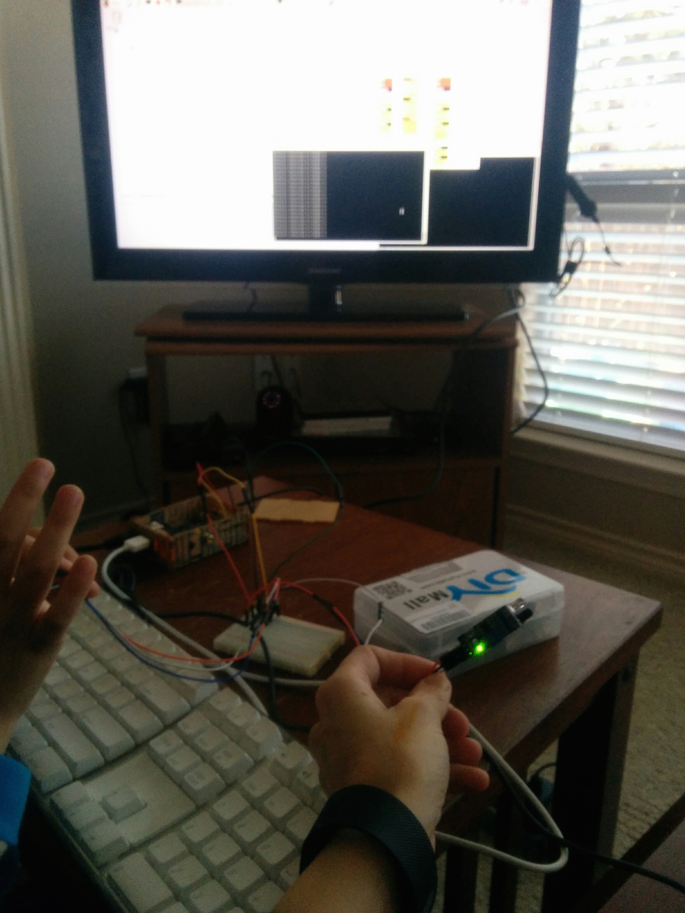
 Next we ran the Python script and played around with changing the time delay so the kids could see that the program was indeed affecting how often statements were being printed to screen. If we set it to 5 seconds, for example, we would count that there really were 5 seconds between print statements. When it was set to 0.1 seconds of course the prints occurred quickly.
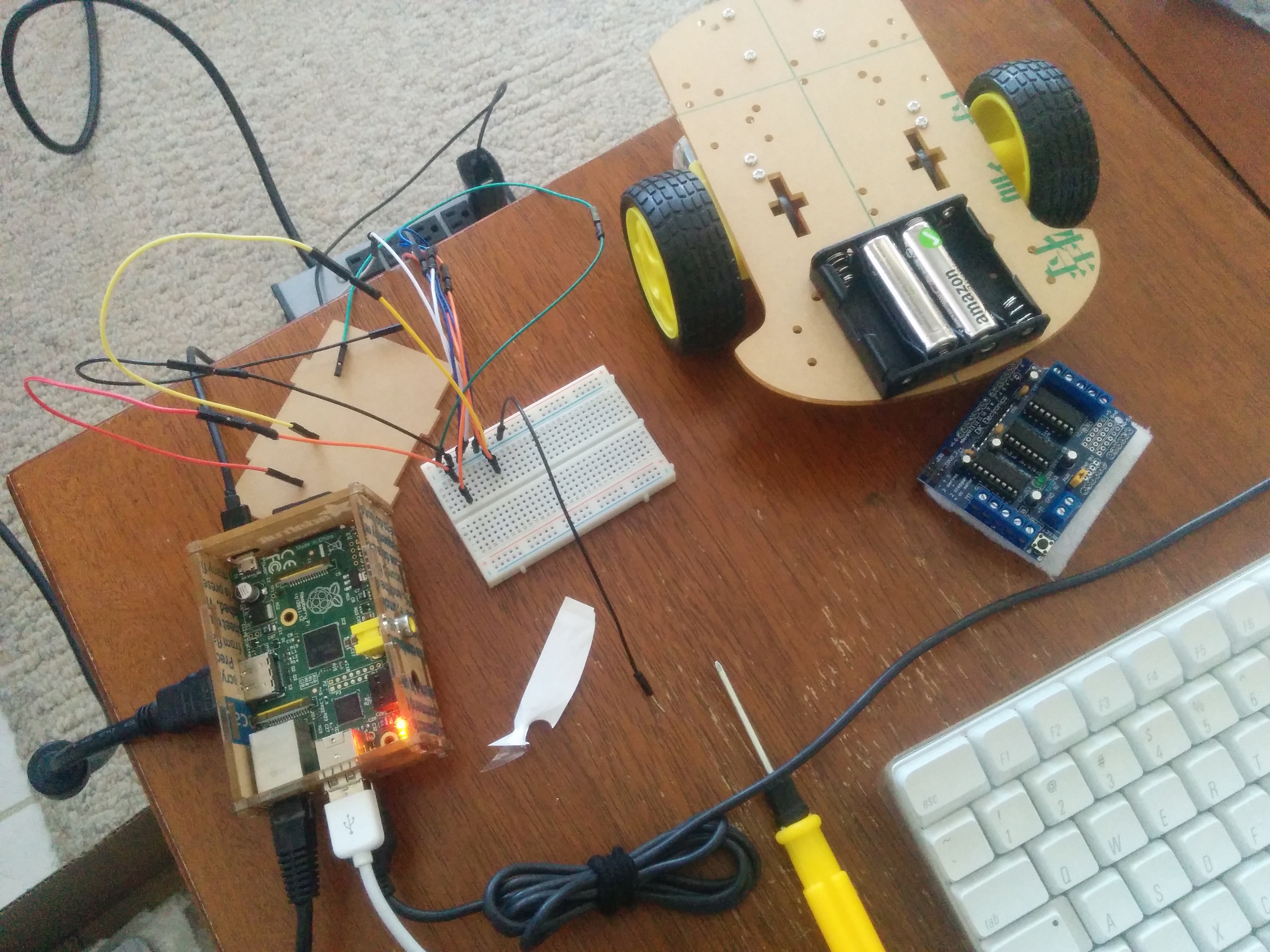
Step 2: Testing the DC motors. As we starting hooking up RP to breadboard to L293D driver board to DC motors, the wires were starting to get unwieldy so we decided to go ahead and attach the wheels and DC motors to the chassis. Then we stuck the driver board to the underside of the chassis and attached the battery pack, breadboard and IR sensors on top. We’ll affix the RP in the end. Now we’re ready to nicely route the wires and test the DC motors.
**Aside: The L293D driver board we initially got has a shift register for programmatically selecting which of the 4 motors to run, so there’s more programming needed than anticipated. I started out with the adafruit tutorial for this part which links to the Adafruit Motor Shield v1 firmware. The AF-Motor library is meant to be used with Arduino. I decided to just rewrite the Python scripts given in the IR sensor robot tutorial I’m following to C++ with help of the WiringPi/C library for controlling the GPIO pins from the RP. We re-ran the C++ version of the IR sensor test, then tried to get the DC motor test working but it wasn’t straightforward and it was time for bed anyway. So the next morning we went to Fry’s and bought this board. We replaced the old board (note that you have to shunt the ENA and ENB pins to the 5V pins next to them if not already shunted) and were able to quickly get up and running. In the end we used the Python script from the original tutorial: motor.py.
The DC motor test passed fine and we were able to move on to completing the robot.
Step 3: Running robot.py and making the robot wireless. While still connected to TV monitor, mouse and keyboard we tried running the robot.py script. It worked without a hitch so we moved on to making the thing wireless.
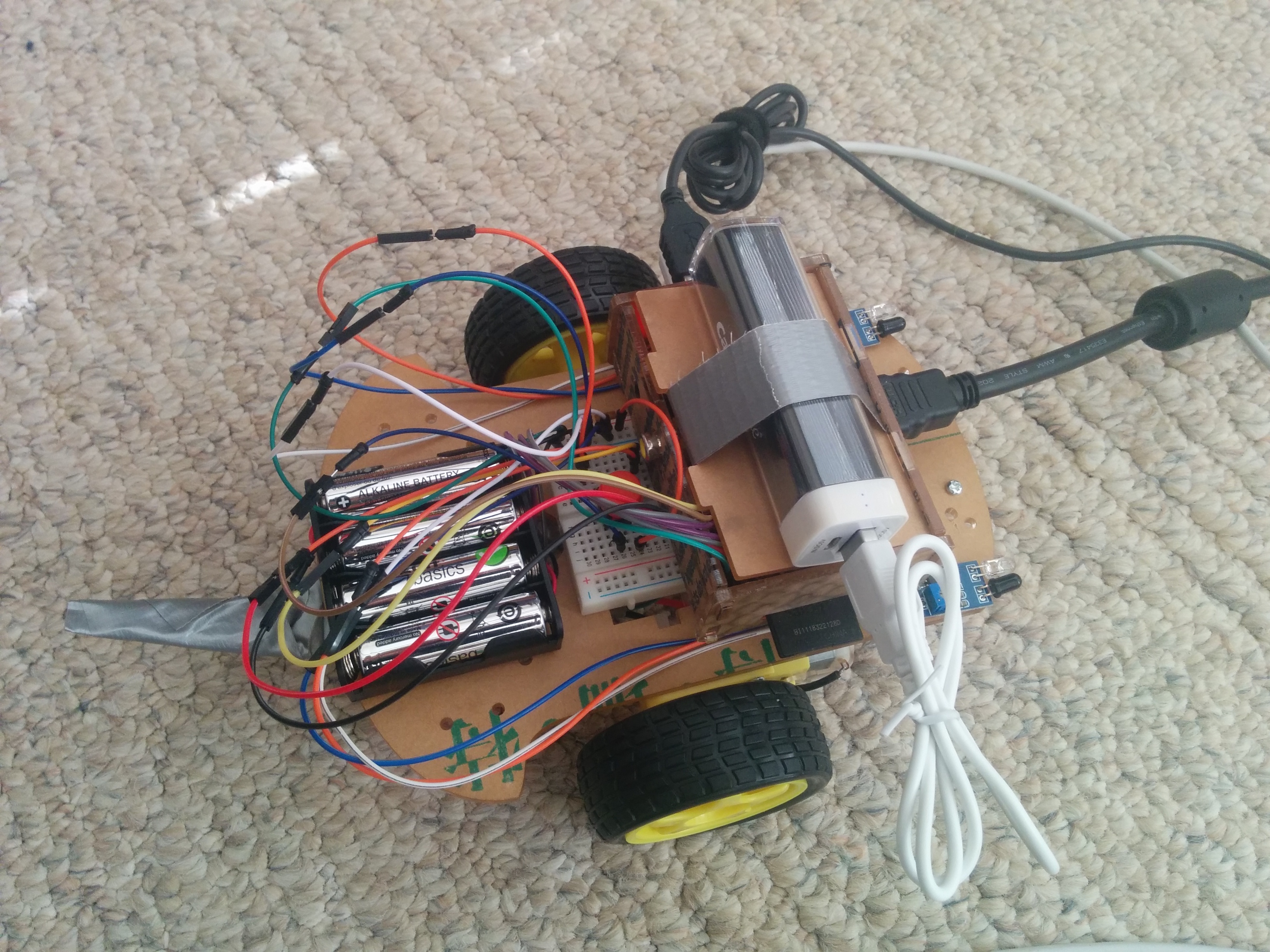
To do this we needed an external power supply for the Raspberry Pi and some way to execute the robot.py script after boot-up. We had a freebie 5V battery for charging a cell phone lying around, so we duct-taped it to the RP cover to make it easily detachable/attachable for charging . Then we added the following line to the /etc/local_init.rc file on the RP:
(sleep 10;python ~/pi/repos/robot/robot.py)&Finally, we shut down the RP, unplugged the AC power adapter, plugged in the 5V battery, and waited for the Raspberry Pi to boot up. Voila, when we push the button our robot does what we expect!
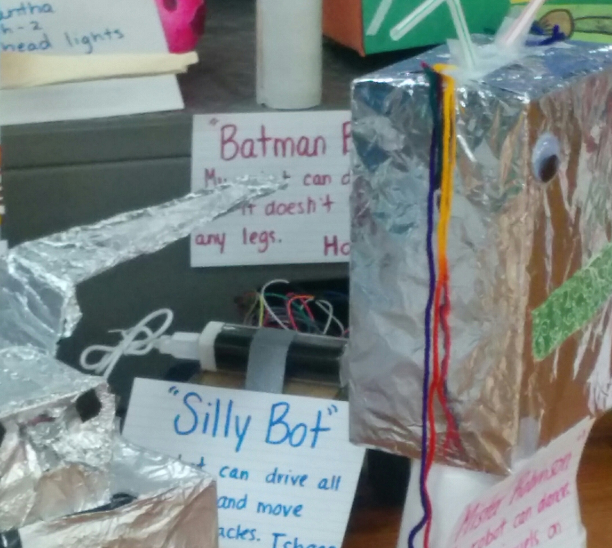
After some experimentation and lots of laughing while watching the robot “try” to get out the front door, head to the toilet, or jaunt over to “play” with some toys, my joyful kids dubbed the robot “Silly Bot.” Here’s Silly Bot hiding behind some other robots:
Here’s Silly Bot in action:
(VIDEO COMING SOON)